") YAT (Yet Another TurtleBot)
YAT (Yet Another TurtleBot)
Wheeled mobile robot design
Wheeled robot design
Wheeled mobile robot configuration selection
#TODO: Dar clasificación de robot móviles
El principal objetivo en el diseño mecánico del robot móvil a desarrollar como solución para la fundación fulgor es obtener una configuración de robot móvil terrestre mecánicamente sencilla, con baja complejidad en su control tal que permita enfocar el esfuerzo en el desarrollo y evaluación de algoritmos de SLAM sin que los aspectos mencionados previamente representen un obstáculo.
Wheeled robots comprise one or more driven wheels and haave optional passive or caster wheels and possibly steered wheels. Most designs require two motors for driving (and steering) a mobile robot.

The design on the left-hand side of the figure has a single driven wheel that is also steered. It requires two motors, one for driving the wheel and one for turning. A disadvantage of this design is that the robot cannot turn on the spot, since the driven wheel is not located at its center. Therefore, the trajectory planning can be more complex than the one for a different configuration.
The robot design in the middle is called differential drive and is one of the most commonly used mobile robot designs. The combination of two driven wheels allows the robot to be driven straight, in a curve, or to turn on the spot. Another advantage of this design is that motors and wheels are in fixed positions and do not need to be turned as in the previous design. This simplifies the robot mechnics considerably.
Finally, on the right-hand side of the figure is the so-called Ackermann Steering, which is the standard drive and steering system of a rear-driven passenger car. It has one motor for driving both rear wheels via a differential box and one motor for combined steering of both front wheels.
A special case of a wheeled robot is the omni-directional Mecanum drive robot, but it is discarded due to the cost and accesibility of such wheels.
One disadvantage of all wheeled robots is that they require a flat surface for driving. Tracked robots are more flexible and can navigate over rough terrain. The main disadvantage, and the reason for not being considered for the project, is that they cannot navigate as accurately as a wheeled robot.
Legged robots are the final category of land-based mobile robots. Like tracked robots, they can navigate over rough terrain, There are many different designs for legged robots, depending on their number of legs. The general rule is: the more legs, the easier to balance. These kind of robots are not considered for the project for being highly complex both mecanically and their control.
The configuration selected for the project is the differential drive, being the most mechanically simple and versatile.
Actuators selection
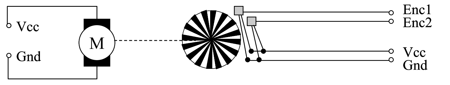
DC electric motors are arguably the most commonly used method for locomotion in mobile robots. Standard DC motor revolve freely, unlike for example stepper motors. Motor control therefore requires a feedback mechanism using shaft encoders.
The first step when building robot hardware is to select the appropiate motor system. For this project, the DC motor available is an encapsulated motor combination comprising a:
- DC motor
- Gearbox
- Magnetic encoder (dual phase-shifted encoders for detection of speed and direction)
Using encapsulated motor systems has the advantage that the solution is much smaller that that using separate modules, plus the system is dust-proof. The disadvantage of using a fixed assembly like this is that the gear ratio may only be changed with difficulty, or not at all. In the worst case, a new motor/gearbox/encoder combination has to be acquired.
A magnetic encoder comprises a disk equipped with a number of magnets and one or two Hall-effect sensors. The encoders to be used in the project have two sensors positioned with a phase shift. Then, it is possible to detect which one is trigered first and this information can be used to determine whether the motor shaft is being turned clockwise or counterclockwise.
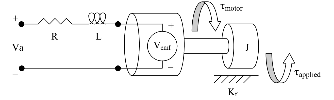
The following figure illustrates a linear model for the DC motor:
The following table contains a list for all relevant variables and constant values:
| Symbol | Description | Units | Symbol | Description | Units |
|---|---|---|---|---|---|
| $\theta$ | Angular position os shaft | $rad$ | $R$ | Nominal terminal resistance | $\Omega$ |
| $\omega$ | Angular shaft velocity | $\frac{rad}{s}$ | $L$ | Rotor inductance | $H$ |
| $\alpha$ | Angular shaft acceleration | $\frac{rad}{s^2}$ | $J$ | Rotor inertia | $kg\cdot{} m^2$ |
| $i$ | Current through armature | $A$ | $K_f$ | Frictional constant | $\frac{N\cdot{} m\cdot{} s}{rad}$ |
| $V_a$ | Applied terminal voltage | $V$ | $K_m$ | Torque constant | $\frac{N\cdot() m}{A}$ |
| $V_e$ | Back emf voltage | $V$ | $K_e$ | Back emf constant | $\frac{V\cdot() s}{rad}$ |
| $\tau_m$ | Motor torque | $N\cdot{} m$ | $K_s$ | Speed constant | $\frac{rad}{V\cdot() s}$ |
| $\tau_a$ | Applied torque (load) | $N\cdot{} m$ | $K_r$ | Regulation constant | $\frac{V\cdot() s}{rad}$ |
A voltage $V_a$ is applied to the terminals of the motor, which generates a current i in the motor armature. The torque $\tau_m$ produced by the motor is proportional to the current, and $K_m$ is the motor’s torque constant:
\[\tau_m = K_m \cdot{} i\]The output power $P_o$ is defined as the rate of work, which for a rotational DC motor equates to the angular velocity of the shaft $\omega$ multiplied by the applied torque $\tau_a$ (i.e. the torque of the load):
\[P_o = \tau_a \cdot{} \omega\]The input power $P_i$, supplied to the motor, is equal to the applied voltage multiplied by the current through the motor:
\[P_i = V_a \cdot{} i\]The motor also generates heat as effect of the current flowing through the armature. The power lost to thermal effects $P_t$ is equivalent to:
\[P_t = R \cdot{} i^2\]The efficienty $\eta$ of the motor is a measure of how well electrical energy is converted to mechanical energy. This can be defined as the output power produced by the motor divided by the input power required by the motor:
\[\eta = \frac{P_o}{P_i} = \frac{\tau_a \omega}{V_a i}\]The efficiency is not constant for all speeds, which needs to be kept in mind if the application requires operation at different speed ranges. The electrical system of the motor can be modelled by a resistor-inductor pair in series with a voltage $V_{emf}$, which corresponds to the back electromotive force. This voltage can be approximated as a linear function of the shaft velocity; $K_e$ is referred to as the back-emf constant:
\[V_e = K_e \cdot{} \omega\]In the simplified DC motor model, motor inductance and motor friction are negligible and set to zero, and the rotor inertia is denoted by $J$. The formulas for current and angular acceleration can therefore be approximated by:
\[i = \frac{-K_e}{R} \omega + \frac{1}{R} V_a\] \[\frac{\delta\omega}{\delta t} = \frac{K_m}{J} i - \frac{\tau_a}{J}\]DC motor driver selection: H-bridge
For most applications we want to be able to do two things with a motor:
- Run it in a forward and backward directions.
- Modify its speed.
Pulse Width Modulation
Pulse width modulation (PWM) is a method for avoiding analog power circuitry by utilizing the fact that mechanical systems have a certain latency. Instead of generating an analog output signal with a voltage proportional to the desired motor speed, it is sufficient to generate digital pulses at the full system voltage level (for example 5V).
By varying the pulse width, we also change the equivalent or effective analog motor signal and therefore control the motor speed. One could say that the motor system behaves like an integrator of the digital input impulses over a certain time span. The quotient $\frac{t_{on}}{t_{period}}$ is called the pulse-width ratio or duty cycle.
Motor calibration
Motor calibration is done by measuring the motor speed ar various settings between 0 and 100, and the entering the PW ratio required to achieve the desired actual speed in a motor calibration table.
Motor calibration is especially important for robots with differential drive, because in these configurations normally one motor runs forward and one backward, in order to drive the robot. Many DC motors exhibit some differences in speed versus PW ratio between forward and backward direction. This can be eliminated by using motor calibration.
Next steps
- Get PWM example with Verilog/Vivado behavioral simulation
- Get plots of motor shaft speed over time and angular velocity vs PW ratio (duty cycle %). Step response